The list of modifications I planned for the Kroma are:
-Change the power LED to an XM-L
-Change the reflector from TIR to an orange peel reflector as seen here
-Change the infrared LEDs to ultraviolet LEDs
-Bore out the battery tube to fit an 18650 battery
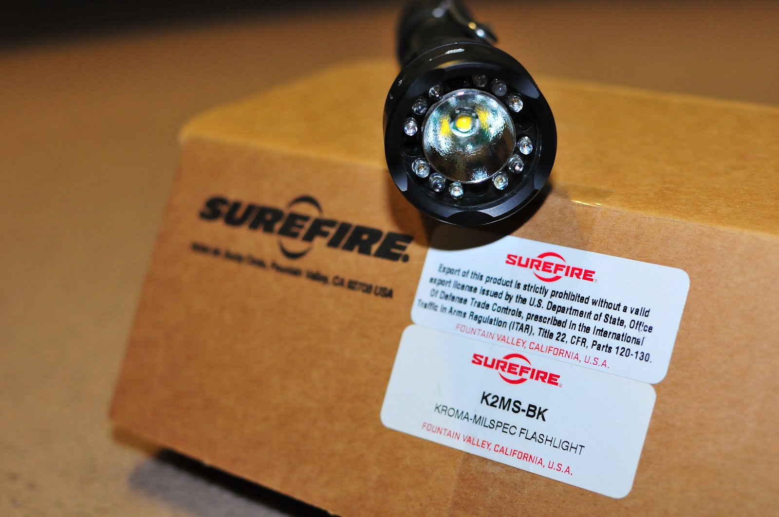
Here's a picture of my Kroma milspec:

LED flashlights have become more efficient and much brighter than those maglites at similar power levels, and LED lights have also become more affordable. One of my LED flashlights, a Jetbeam 3M XM-L, running off of a rechargeable lithium ion battery can put out around 450 lumens for about an hour and a half, whereas a 3-D cell incandescent maglite can maybe put out about 1/4 as many lumens, and I couldn't find any information on battery life, but I'd guess it's longer than the rating of the LED light. If you need the brightness, I think LED lights are better because they convert most of the energy from the battery into light, instead of producing lots of heat along with the light. Incandescent lights turn much of the energy from the battery into heat in addition to the light. There is still heat being put out by the LED bulb, but for 450 lumens, I would expect some. If you want the battery life, the the maglite seems to be the better choice. However, with he Jetbeam 3M XM-L flashlight, you can change the brightness level to anything between 0.3 lumens to 450 lumens, select a defensive strobe mode, or choose an SOS mode because a microchip is built into the circuit board of the light. The light is blinding to begin with, and a strobe will most likely disorient anyone you point it at. In the dimmest light level, which would be useful for night, the battery life for the 3M is rated at 200 hours.
Now, onto the Surefire Kroma. I've always thought Surefire lights were overpriced and underpowered. Surefire flashlight lumen ratings are lower than lumen ratings from brands such as Jetbeam, Sunwayman, or 4Sevens. I don't own any Surefire lights other than the Kroma because it's is the only light I could find that has a white LED and color LEDs built into one flashlight. I don't see myself buying any other Surefire lights, but from what I've heard, the price you pay for the lights is because of their excellent customer service. If your light has problems and it's their fault, you can send it in for a free repair or replacement. Some other information I've heard about Surefire is that they under-rate their flashlight lumens, so the ratings on their site are probably lower than the actual amount of lumens put out.
There are two models of the Kroma I have seen and various types of PKEF, or Paul Kim Experimental Flashlight, models. Paul Kim is the engineer and designer of Surefire lights and holds many patents regarding flashlights. The PKEF lights are prototypes with many different variations, from blue and green 3mm LEDs to 5mm color LEDs housed in a larger head that can accommodate the power LED and the larger LEDs. A google search of "pkef light" will give you a handful of sites showing the models. As for the Kromas that made it past the prototype stage, there is a civilian model and a military spec model. The civilian model has a white power LED, 8 red T1, or 3mm LEDs and 8 blue T1 LEDs. The color LEDs are arranged in a circle surrounding the reflector of the power LED. There are 5 modes which can be selected with a magnetic ring built into the lights, and the modes are different for the civilian and milspec models. These are the civilian model modes in the order you can select them from left to right: high blue, low blue, white, low red, high red. When in the white mode only, you can choose between 2 brightness levels by pressing the two-stage tailcap button. A lighter press will give you a low power white mode, and fully pressing the tailcap button will give you the high power white mode. Tightening the tailcap will allow you to keep the light constantly on in low or high mode, depending on the amount you twist the tailcap. There is a resistor built into the tailcap that controls the low power white mode, but I couldn't take the tailcap apart so I couldn't check out the setup in the tailcap. The civilian model is no longer on sale by Surefire, but sites like eBay and Amazon may have them.
The milspec Kroma information page can be viewed here. It has 5 types of lights instead of the 3 in the civilian model. There are white, yellow-green, blue, red, and infrared LEDs installed. All colors except the white LED are T1 LEDs. I think the standard power LED emitter is a Luxeon, but I'm not sure. I planned to replace it anyway and decided to try a CREE XM-L emitter. I was planning on making any modifications I did permanent, so I got the brightest LED on the market and found Arctic Alumina adhesive to keep the LED in place. The Arctic Alumina adhesive is nonconductive and noncapacitive, so it's perfect for holding the emitter in place and holding the reflector in place as well. I wanted a warmer colored light than the usual blueish-white colors that LEDs put out, so I looked around and found this emitter. It's the XM-L emitter already mounted on the smallest heat sink I could find, and I figured I could use a dremel or sandpaper to grind down the size of the heatsink if it didn't fit in the light.
The first step I took was removing the selector ring. I had read on forums that the selector ring contained a delicate part that could break easily. I followed the instructions here and got the selector ring off with moderate difficulty. There are three sections to the head. You should be able to unscrew the first section, the section at the front of the light, by hand. The second section is held to the third section by Loctite or some brand of threadlocker. It's not going to budge if you try to unscrew it by hand. I used a butane torch and a couple vise grips with the teeth wrapped in duct tape to prevent scratching, but I found out there wasn't as much tape as I needed so there are some battle scars on the Kroma head.
Here's a picture of the flashlight body with the three sections of the head taken apart. I took the retaining ring off of the LED module and removed the LED module from the rest of the circuit board. You might be able to see the scratches on the middle section from when I took the light apart.

Anyway, now I won't have to worry about keeping the light nice and pretty. This site is where I found the method to remove the middle section from the rest of the head. You probably wanna use heat resistant gloves because the head will get hot; I heated mine up to about 260 degrees Fahrenheit before it began to unscrew. I used a contactless infrared thermometer to find this temperature. There is a plastic retaining ring that holds the T1 LEDs and the TIR reflector in place. The middle section holds this retaining ring in place, so as you heat the middle section you also have to remember that you can't heat it too much because the retaining ring may melt. I was lucky and only went a little bit past the melting point of the ring, so there was a little bit of the ring that melted, but I smoothed the imperfections by shaving them off with an x-acto knife. To get that middle section off after I heated it, I clamped the vise grips on the area where the selector ring was and on the middle section. You'll need to apply a good amount of torque to get the sections to unscrew.
Getting the head separated into its three sections is one of the hardest parts or the hardest part if all you want to do is change the colored LEDs. If you are going for changing the power LED, like I was, another tricky part will be removing the power LED from the heat sink. You're already so far you might as well change the power LED and get more brightness out of the flashlight. There are two sections to the flashlight circuit board. One holds the power LED and color LEDs and is held to the other part of the circuit board by contact pins. The other part of the circuit board is screwed into the part of the light where the selector ring surrounds it and has magnetic sensors that sense where the magnet in the ring is to change the LED setting accordingly. That part of the circuit board is held down by hex screws on the milspec version and phillips screws on the civilian version. There isn't really any reason to unscrew the part of the circuit board that controls switching unless you want to tweak it, and it seems that you'll need some good electrical knowledge and a very fine pencil soldering iron to do so.
In this picture you can see the Cree XM-L emitter and the Mcr20S reflector. There are 4 color LEDs missing, the infrared ones, because I'm waiting for UV LEDs to come in the mail. Sorry, but I had already glued the reflector so I don't wanna remove the reflector to show the bare emitter and go through the trouble of reattaching the reflector.
The power LED is soldered to the circuit board and held onto the heatsink by some type of adhesive. It took a good amount of force with needlenose pliers to remove the power LED after desoldering the connections. If this part doesn't sound that hard, just know that you'll have to desolder the power LED while avoiding touching the color LEDs. The heatsink can't be removed until all the color LEDs are removed and until the power LED is desoldered from the circuit board as well, so it's easier to try to remove the power LED first and save the work of removing 16 LEDs. The color LEDs block the heatsink from moving, and as long as the power LED is soldered to the circuit board, it stops the heatsink from moving as well. Excessive pulling on the heatsink without desoldering the power LED will definitely rip off contacts on the LED or the circuit board. Desoldering the power LED is tricky if you decide to leave the color LEDs attached because if you touch the iron to the emitter ends of those LEDs, they'll melt. If you do decide to remove the color LEDs, just don't forget to write down where they go and which direction the polarity must be. You should also mark the LEDs so that you can solder them back at the correct heights.
A compatible replacement LED for the power LED is a Seoul Semiconductor P4 LED. I was thinking about using a Seoul but decided to try an XM-L and just get a Seoul if the XM-L didn't work. I really wanted to change the reflector because the TIR reflector basically magnifies the LED die, and you get a box-shaped beam, which I don't like. I wanted a smoother beam, so I wanted to get an orange peel reflector, and I saw this forum thread where a user installed a Seoul Mcr20 reflector, so I looked for the same reflector and found an Mcr20S reflector. It's $14, but you also have to pay $14 for shipping. I also ordered a Mcr20J from here, but the Mcr20J doesn't fit as well as the Mcr20S does, so I sent the J version back. The Mcr20S reflector is made specifically to work with the Seoul P4 emitter, so if you want to make sure your LED/reflector combination works, get a P4 and an Mcr20S. I used data for the XM-L and the Mcr20S to find out whether the LED would fit. The diameter of the opening on the Mcr20S is 7mm and the dimensions for the XM-L emitter are 5mm x 5mm. I also used my Jetbeam 3M to estimate where the reflector should be placed to reflect light efficiently since the 3M also has an XM-L emitter. The Mcr20S opening is just large enough to fit around the LED die, and You'll have to move the reflector around vertically to find the optimum position that will reflect the most light from the emitter. You'll need an adhesive to hold the reflector in place because the heatsink is really only shaped to hold TIR lenses. This is where the Arctic Alumina adhesive comes in. It's a two part epoxy that cures in 5 minutes and seems to hold strongly. The Arctic Alumina adhesive is actually for computers, but the fact that it's nonconductive and noncapacitive made it ideal for using in the light because the reflector would short circuit the batteries if there were no adhesive. Since the heatsink is so small, the contacts are very close to the LED. There isn't any room to attach the reflector without touching both contacts, so the adhesive insulates the contacts and prevents the reflector from shorting the batteries.
In these pictures, you can see that I got the XM-L emitter centered and positioned pretty well:


Changing the color LEDs is relatively easy. You can use desoldering braid to remove the solder and make it easier when removing the LEDs, or you can touch the soldering iron to both pins at the same time and pull the LED out. I did it the second way, and you just need to watch out for other components on the circuit board. Everything is so close together that you might burn a resistor with the iron. Watch the polarity when putting LEDs back in and you should have no trouble at all when switching LED colors. I changed out the green LEDs with these green LEDs, and I replaced the IR LEDs with these Bivar 390 nm UV LEDs. I changed the green LEDs, because I didn't like the beam pattern of the original green LEDs and figured I would try and find LEDs that were around the same color but had a better beam pattern. The green and red LEDs are good for preserving night vision, the blue LEDs are good for tracking blood, and the UV LEDs can be used in many different types of applications. I picked up this UV pen, and it works pretty well. The ink doesn't wash off easily and reacts to the UV light. You can use the UV pen to mark your belongings and identify them when necessary.
Boring out the battery tube to fit an 18650 battery the way I did is long and time-consuming, but if you really want to be able to use 18650s instead of Cr123a batteries, then you can either send the battery tube to a company that will bore it or try and bore it out yourself. The boring service for the Kroma that I found was about $50-$60, so I decided to try and find another way to bore out the battery tube. I somehow found this youtube video that shows how to bore out a Surefire 6P battery tube to fit an 18650 battery, and used the same technique to bore out my Kroma. First, I put about 5 or 6 layers of duct tape around a 5/16 inch drill bit then taped a piece of 150 grit sandpaper onto the bit. For the sandpaper, I cut a piece that was longer than the battery tube and that was a little shorter than the diameter of the duct taped drill bit. I used wet/dry sandpaper and ran water on the battery tube because the heat generated can burn you if you try to bore the tube dry. I ran the drill and moved it back and forth in a sawing motion. Try not to apply any force in any direction except forwards and backwards because you might bore the tube crooked if not. When the sandpaper seemed to move back and forth easily inside the tube, I placed a short strip of duct tape at the back, or the end closest to the drill, and then did the same sawing motion to gradually bore the hole bigger. I would place more and more small strips closer and closer to the front as the hole became wider. Then I would repeat the same steps again with the next layer of duct tape. If you try to rush the process and put more than layer of duct tape at a time, you'll probably need a vice to hold the battery tube or else the sandpaper will get stuck and it's a pain in the ass to try to get the battery tube off of the drill bit. It took me about 8 hours in all to bore out the tube, and I went through about 8 drill batteries. After boring the tube, you may want to take the same kind of dremel tip used in the youtube video to smooth out the inside of the tube.
Here's a picture of the Kroma milspec with an Eagletac 3100 mAh 18650.

***There is one thing you should know about boring out a Kroma battery tube, civilian or milspec: The two stage switch will not function properly unless you leave a lip on the end where the tailcap screws on. I took apart a Kroma tailcap and found that there are 2 resistors in a circuit board in the tailcap that create resistance of about 5.5 ohms. There are three prongs on the circuit board that drop resistance to almost zero when they make contact with certain points on the circuit board. This is why the light is able to engage a low mode and a high mode. When you bore out the Kroma battery tube and don't leave a lip, the diameter of the tube is wider than the diameter of the circuit board, so the prongs won't touch the circuit board when the tailcap is screwed all the way down. The circuit board is still able to make contact with the battery tube, so low mode will be engaged. On the civilian Kroma, low mode engages the low white LED and all the modes of color LEDs depending on the position of the selector ring. High mode on the civilian Kroma engages the high white LED regardless of the position of the selector ring. Low mode on the milspec Kroma engages the low white LED and all of the color LEDs. High mode doesn't function the same way as the civilian Kroma; high white will only engage in white mode. High mode for color LEDs will only engage those LEDs and not the white LED. I think this is more convenient and thinking about when the flashlight would be used in a combat situation, it could be deadly to accidentally engage the high white mode. In other words, if you bore out the battery tube and don't leave the tailcap end of the battery tube at its original diameter, you lose the high power mode of the white LED. To fix this, you can get a different tailcap, but you will probably lose the low power mode of the white LED. I would probably use the low power white beam at night, but since I can't control the brightness without changing the resistor, I probably wouldn't use the low mode as much and would be fine giving it up. I also have the color LEDs which can be more effective when preserving night vision. When I need a moonlight beam, I would use the Jetbeam 3M since the brightness is infinitely adjustable.
The almost finished light:
I'm probably gonna get a different tailcap to fix the low/high white issue but for now, here's low white mode with the 4000K XM-L

Green mode

Blue Mode

Red Mode

UV mode

Low white beamshot from about 1 meter away

Green beamshot from about 1 foot away

Blue beamshot from about 1 foot away

Red beamshot from about 1 foot away

UV beamshot from about 6 inches away

I started work on the Kroma around the beginning of May, and after about half a month, the light is almost finished. If it weren't for the tailcap problem, the Kroma milspec mod would be done, but I'm waiting for a tailcap to come in to see if it will work with the Kroma. It's a reverse clicky switch, so I won't have a low white mode, but I'll have the other colors for night illumination, and I'll be able to use a clicky instead of the twisty tailcap the Kroma currently uses. For the scratches I made on the middle section of the head, I could just leave them, or a friend told me to put some heat shrink tubing on the head. The tubing would protect the head from further damage if dropped in addition to hiding the scratches. However, I don't know if heat from the XM-L will become an issue, because if it does, the tubing might act as an insulator.
Future hikes include: true manamana, the kalihi saddle, and the pali notches. I'm waiting for Kevin to free up so he can take me on those hikes. I might also check out the stairs to get some exercise. I've been running with Mitsuo, and we've run Wilhelmina rise as well as a side road that links up with Wilhelmina rise. We're planning on trying runs where we explore and find new scenery.
Update 5/31/12:
I found a Surefire Z59 clicky tailcap on ebay and retrofitted the click mechanism into the Kroma tailcap. If it didn't work, I could always just use the Z59 tailcap instead, but I wanted to try to keep the look of the Kroma as original as possible. Other than the scratches I made when I took apart the head, the Kroma looks like a normal Kroma now. The Z59 tailcap is a reverse clicky switch, as opposed to the twisty switch that comes in the Kroma's tailcap. Since the Z59 is the tailcap that comes with the U2 flashlight, I figured it would be my best bet to try to get a clicky mechanism that wouldn't be too small. Since I bored out the battery tube of the Kroma to fit an 18650, the mechanism in the twisty cap that controlled low and high power white modes could only engage the low mode, and I lost the high power white mode because the diameter of the mechanism was a little smaller than the diameter of the bored-out tube. I read that the stock first and second generation U2 lights could take 18650 batteries, so the Z59 switch would probably have a large enough diameter to make contact with the battery tube.
Taking the Z59 switch apart is really easy; all you need to do is unscrew the top portion of the cap and you can access the clicky switch and rubber nub. Taking the Kroma tailcap apart is a different story. It seems that Surefire didn't expect or want people to take the tailcap apart because there are several different components that make up the complicated mechanism in the tailcap, and all are glued together. I didn't know how to get the top part of the switch off and ended up breaking it when I was trying to pull it apart with pliers. The top part is the part of the switch that you push when you press the button on the tailcap and is made of plastic. It looks like the top part is glued or melted into the rest of the mechanism because I tried heating it and pulling on it, but it didn't budge. I just gave up and figured if I broke it I could super glue it back.
The clicky mechanism in the Z59 has a lip that keeps it from falling out when you take the tailcap off of the light to change batteries. I used sandpaper to grind this edge down so it could fit in the Kroma tailcap since the Kroma's tailcap doesn't come apart at all. After much sanding, I got the diameter down to a good level and was able to push the mechanism into the Kroma's tailcap. There is enough excess on the mechanism to keep it in the tailcap so I didn't have to glue it. I used some parts I had lying around to extend the button of the clicky mechanism since it was too short to stick out by itself. After reassembling everything, it was the moment of truth - I pressed the button and the high mode came on. The light is finally finished and at the expense of losing the low white mode, I have a modded flashlight that has everything I wanted:
-4000K Cree XM-L LED
-Red, blue, yellow-green and UV LEDs
-Bored out battery tube that accepts 18650 batteries
-Reverse clicky switch retrofitted into the original tailcap that allows for easier momentary and constant on
Here's an inside view of the tailcap:

Here's the finished light:


awesome job if u ever decide to sell it or make one for others, im interested in doing that to my kroma, email is genius5th@yahoo.com
ReplyDeleteThank you very much!
ReplyDelete